Brilliant Strategies Of Info About Is TTL Always 5V

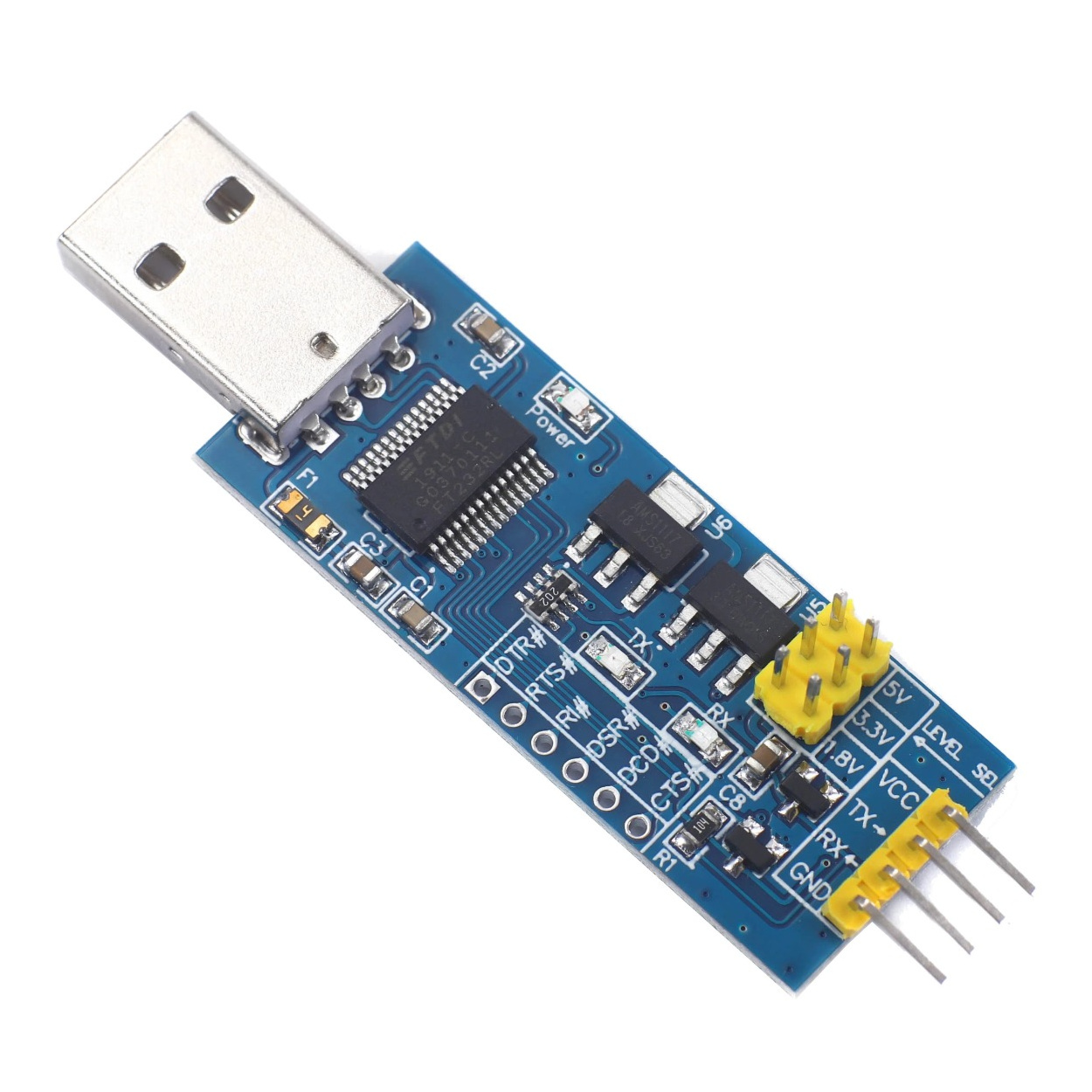
Probots FT232RL USB To Serial TTL Board Support 5V 3.3V 1.8V Level
Delving into TTL Logic
1. Understanding TTL Voltage Levels
So, you're diving into the fascinating world of Transistor-Transistor Logic, or TTL for short. That's great! It's the foundation of so much digital electronics. And you've got the big question on your mind: "Is TTL always 5V?" Well, buckle up, because the answer isn't quite as straightforward as a simple yes or no. It's more like a "mostly yes, but with a few caveats" kind of situation.
Historically, TTL circuits were designed to operate primarily on a 5-volt power supply. This voltage level became somewhat of a standard. When you saw "TTL," you generally assumed it meant 5V. This 5V standard was what allowed all sorts of different TTL chips to work together without frying each other (or, at least, with a significantly reduced risk of frying each other). Think of it as a common language the components could understand.
But, as technology marches relentlessly onward, things have evolved. While classic TTL operates around 5V, newer logic families have emerged to meet the demands of lower power consumption and higher speeds. These newer families, often still inspired by TTL principles, don't necessarily stick to the 5V rule. They're the rebellious teenagers of the logic world, forging their own path (and voltage levels).
So, while 5V is the classic and often the default assumption for TTL, it's crucial to always check the datasheet for the specific chip you're working with. Datasheets are your friends; they tell you everything you need to know (and often a whole lot more!).

TTL Voltage Ranges
2. Defining Logic Levels
Even within the 5V realm, TTL doesn't consider exactly 5V to be a "high" signal and exactly 0V to be a "low" signal. There's a range involved, and it's important to understand these ranges to ensure your circuits function reliably. A logic "high" typically falls between 2.0V and 5.0V, while a logic "low" is generally between 0.0V and 0.8V. These ranges provide a "noise margin," which is basically a buffer zone to protect against unwanted voltage fluctuations. If your "high" signal dips below 2.0V, or your "low" signal creeps above 0.8V, you might start experiencing unpredictable behavior. Think of it as trying to understand someone who's mumbling or shouting; there's a point where the message gets lost.
Why the wiggle room? Well, real-world circuits aren't perfect. There's always some amount of noise or interference that can affect the voltage levels. The noise margin accounts for this, ensuring that the logic gates still interpret the signals correctly, even with a bit of fuzziness. Without these margins, your digital circuits would be about as reliable as a weather forecast.
Now, you might be wondering, "What happens between 0.8V and 2.0V?" That's the "no man's land," the twilight zone of TTL. A voltage in that range is undefined, and the behavior of the gate is unpredictable. It might interpret it as a high, it might interpret it as a low, or it might just get confused and sulk. The key is to avoid that range altogether to prevent headaches down the line. Keep your signals clearly high or clearly low.
These thresholds are vital for understanding how TTL interacts with other components. It is crucial to verify your input and output voltages comply with the defined voltage range so your circuits functions as designed.

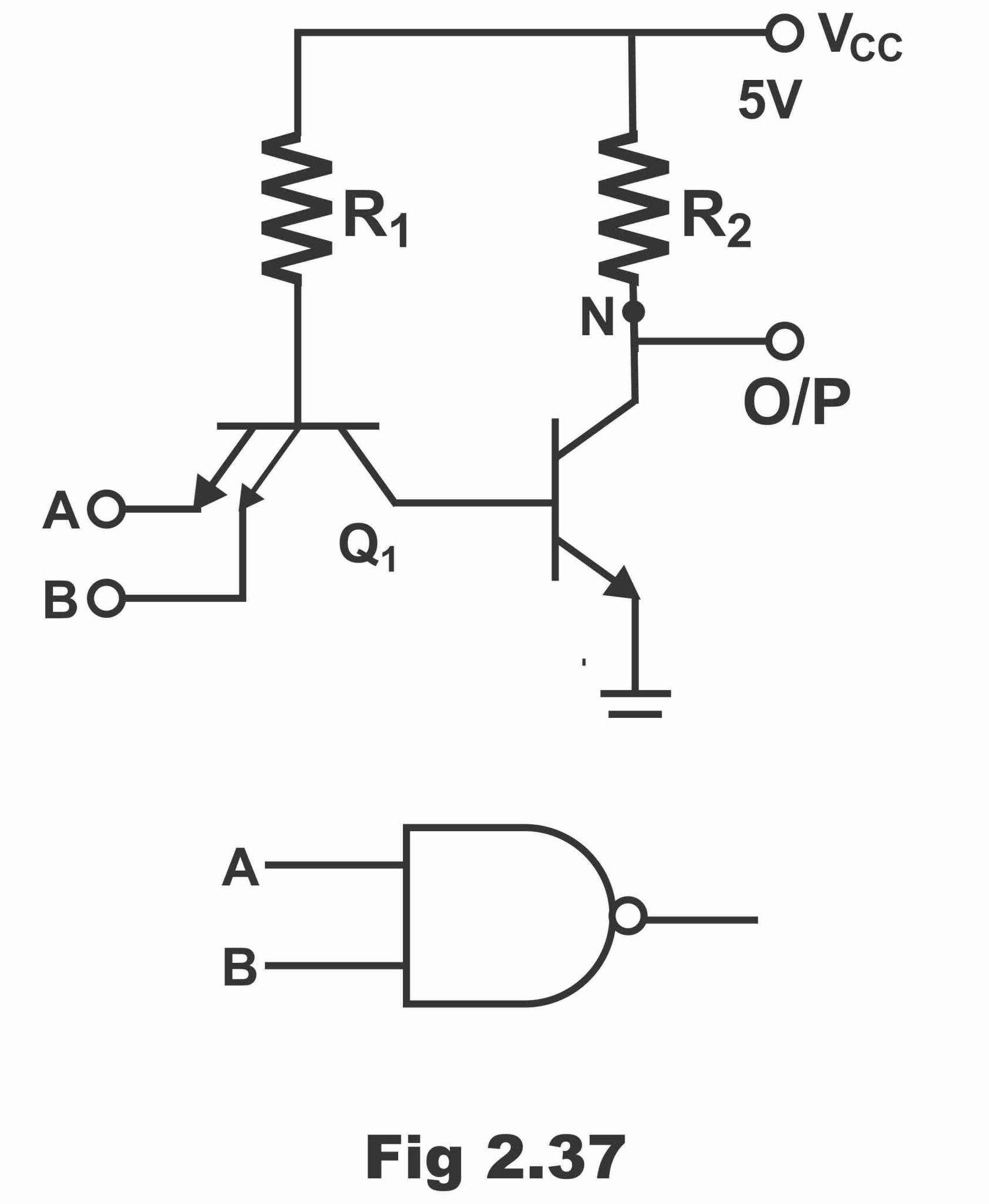
TTL Circuit Transistor Logic Operation
Beyond 5V
3. Exploring Alternative Voltages
The quest for lower power consumption has led to the development of TTL-inspired logic families that operate at lower voltages, such as 3.3V and even lower. These lower voltage families offer significant advantages in terms of power efficiency, making them ideal for battery-powered devices and other applications where minimizing energy consumption is paramount. Think of your smartphone; it wouldn't last very long if it were running on old-school 5V TTL!
These lower voltage logic families often use similar circuit designs as traditional TTL but are optimized for operation at the reduced voltage. This means that while the underlying principles are similar, the specific voltage thresholds and other characteristics will be different. So, again, always consult the datasheet to understand the specific requirements of the logic family you're using.
The shift to lower voltages has also been driven by the need for faster switching speeds. Lower voltages generally translate to lower capacitance, which in turn allows for faster switching times. This is crucial for high-performance applications where speed is critical. Imagine trying to play a modern video game on a computer from the 1980s; it simply wouldn't be able to keep up.
Because of the emergence of new standards, many chips are now designed to handle dual-voltage operation, offering a flexible blend of legacy and new technology. Be sure to understand each component's voltage requirements to be sure they are compatible.

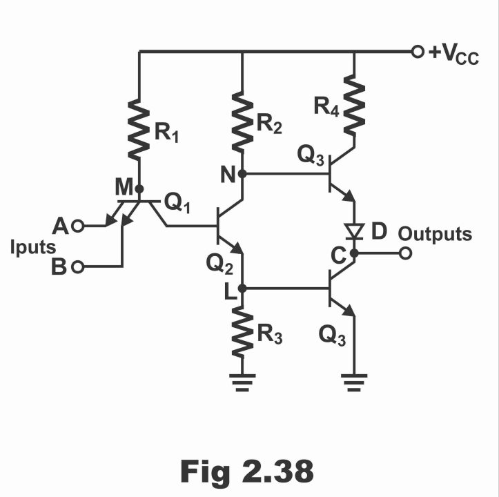
TTL Circuit Transistor Logic Operation
Interfacing TTL with Other Logic Families
4. Bridging the Voltage Gap
So, what happens when you need to connect a 5V TTL circuit to a 3.3V logic circuit? Can you just directly connect them? The short answer is: usually not! Directly connecting them can lead to damage or unreliable operation due to the voltage mismatch. It's like trying to plug a European appliance into an American outlet without a converter; sparks will likely fly (and not in a good way!).
The solution is to use level shifters. Level shifters are special circuits that convert voltage levels from one logic family to another. They act as a bridge between the different voltage domains, ensuring that the signals are properly translated. There are different types of level shifters available, each designed for specific applications. Some are unidirectional, meaning they only convert signals in one direction, while others are bidirectional, allowing for communication in both directions.
Choosing the right level shifter depends on the specific voltage levels you need to convert between, the speed requirements of your application, and other factors. Again, datasheets are your friend! They'll provide you with all the information you need to select the appropriate level shifter for your needs. You can even use resistor dividers or transistors to adapt the circuit levels, depending on the requirements.
When mixing logic families, careful planning and the use of level shifters is key to ensuring proper operation. Failing to do so can result in damage to components, intermittent failures, or just plain unpredictable behavior. It's always better to be safe than sorry!

Transistor Logic Ttl Family Nand Gate In
FAQ
5. Your Burning Questions Answered
Still got questions about TTL voltage? You're not alone! Here are a few frequently asked questions to help clarify things:
Q: Can I power a 5V TTL chip with a 3.3V power supply?A: Nope! 5V TTL chips are designed to operate at 5V. Supplying them with 3.3V will likely result in them not working correctly, or potentially even damaging them. It is like trying to drive a car with insufficient fuel; it simply will not work.
Q: What happens if I apply 5V to a 3.3V logic input?A: Bad things! Applying 5V to a 3.3V input can damage the chip. 3.3V logic inputs are not designed to withstand voltages higher than their rated voltage, and exceeding that voltage can cause permanent damage. You will release the magic smoke, and it's usually a sign of bad things happening.
Q: Are there any modern TTL chips that still use 5V?A: Absolutely! While lower voltage logic families are becoming increasingly popular, there are still plenty of 5V TTL chips available and used in many applications. 5V TTL remains a viable option, especially in situations where compatibility with legacy systems is important.
